The measured model
The third attempt kept the recovered cameras and scale from chapter 2, but this time the design was done by Claude, Anthropic's AI model, working as a coding agent on the same computer. Claude wrote the alternator as a CAD program, the way an engineer builds a part in a CAD package: turned housings, a grooved pulley, round mounting pillars, 48 cooling fins, and vent windows traced from the photos and cut through the castings. Every change was scored against all three photos and kept only if the score improved.
Loading model…
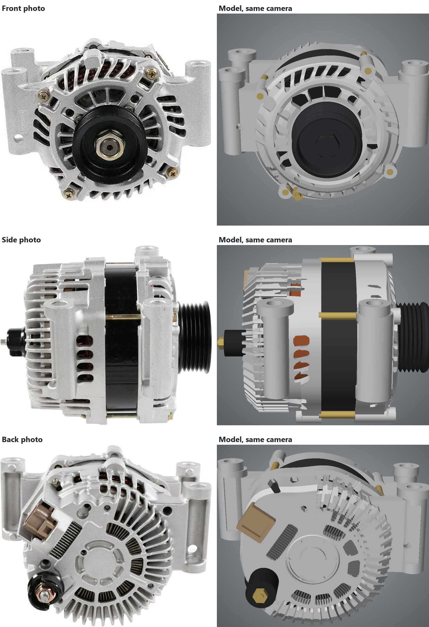
Each photo next to the model
How it was built
- Recover the camerasVGGT, Meta's 3-D vision model, worked out where each photo was taken from and produced a rough point cloud, as in chapter 2.
- Find the scale without measuringThe 6-rib pulley's grooves are 3.56 mm apart. Claude measured that spacing in the side photo (18 pixels), which sets the size of everything else.
- Design it as real CADClaude wrote a Python program in which every part is a proper solid with named dimensions. The solids are built and combined by manifold3d, an open-source solid-modelling library, the same way a CAD package builds a part.
- Score every change against the photosA scoring program, also written by Claude, draws the model from all three recovered cameras and compares it with each photo on outline, edges and surface depth. A change stays only if the whole model scores better.
Who and what did the work
| Tool | What it is | What it did here |
|---|---|---|
| Claude (Anthropic), in Claude Code | An AI model working as a coding agent on this computer: it reads images, writes and runs programs | Studied the photos, decided what to measure, wrote and revised the CAD program and the scoring program, and ran every measurement |
| VGGT-1B (Meta) | A 3-D vision model, run locally | Recovered the three camera positions and a point cloud of the visible surfaces |
| manifold3d | Open-source solid-modelling library | Built the solids and cut the openings |
| OpenCV, NumPy, SciPy | Open-source image-processing and maths libraries | Found the edges in the photos for scoring, and fine-tuned dimensions to fit the photos |
| three.js | Browser 3-D library | Draws the rotatable model on this page |
| The project's owner | The human behind the project | Took the photos, reviewed each version, and spotted three flaws the scores had missed |
Getting from first draft to this
Claude's first versions (v1 to v4) used cameras it solved itself from landmark points (bolt heads, the shaft centre, the tops of the mounting holes) that it located in each photo by pixel position. They had the right parts in roughly the right places, but they were judged mostly on outline, and outline hides a lot. At v5 the model moved onto the VGGT cameras. Then the project's owner compared the model with the photos and pointed out three things Claude had missed: the mounting pillars were square instead of round, the B+ battery terminal on the back was the wrong shape, and the front face was a flat plate where the side photo shows it stepped. Claude measured and fixed each one, and one fix corrected an earlier "fix" of its own: shortening the terminal scored worse, because its length had been right and its shape wrong.
| Version | What changed | Outline match | Edges matched | Depth error |
|---|---|---|---|---|
| v5 | Claude's CAD moved onto the VGGT cameras | 94.5 % | 52 % | 4.90 mm |
| v6 | Scorer in charge: depth and edges, not just outline | 94.4 % | 53 % | 3.17 mm |
| v8 | Round pillars, full-length fins, refitted B+ terminal | 95.1 % | 55 % | 2.79 mm |
| v10 | Stepped front face, vent windows, fitted pulley | 96.1 % | 61 % | 2.43 mm |
Averages over the three photos. The outline barely moved after v5; the depth error halved and the share of real edges reproduced kept climbing. Changes that scored worse, such as full-width front plates or deeper fins, were thrown out.
How close it is, photo by photo
| Photo | Outline match | Edges matched | Edge precision | Depth error |
|---|---|---|---|---|
| Front | 96.8 % | 73.7 % | 79.7 % | 2.15 mm |
| Side | 95.6 % | 56.4 % | 59.5 % | 2.67 mm |
| Back | 96.1 % | 53.7 % | 63.4 % | 2.46 mm |
The gaps that remain are mostly fine casting detail: small ribs, bosses and what's inside the vents.
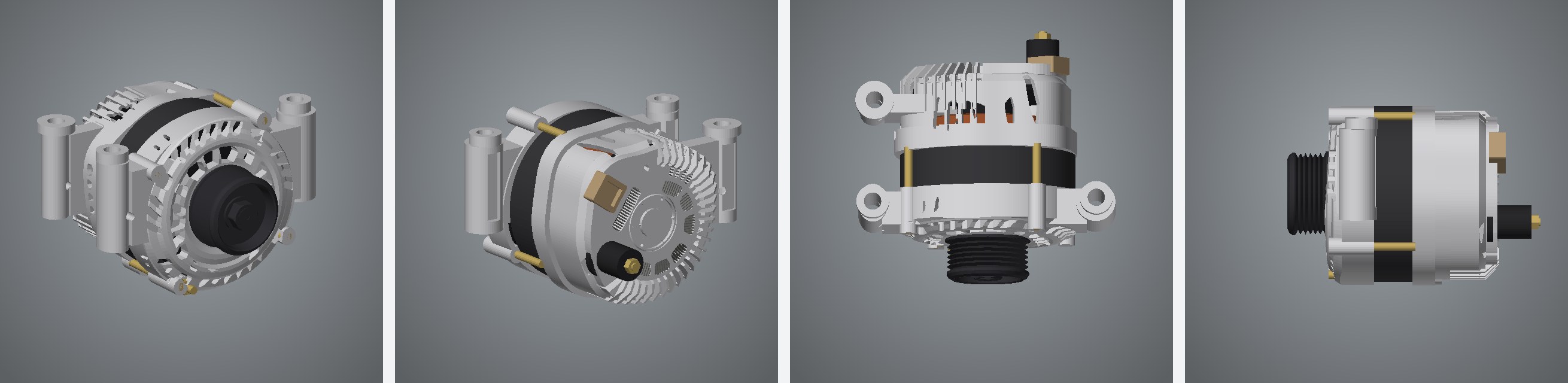
From angles no photo shows
Design like an engineer, check like an inspector.
Neither guessing nor generic shapes got there. Real construction plus a measured check of every change against every photo did. The next step is to teach the automatic pipeline from chapter 2 to design this way for any part.
What to keep in mind
Measured where it was seen
Everything visible in at least one photo is measured from it. The top, the bottom and the unphotographed side are reasonable fill-ins.
Materials are generic
Cast aluminium, black-coated steel, brass, copper and plastic are standard material settings, not colours taken from the photos.
Designed step by step, this time
Claude made each design decision in turn and checked it with the measuring tools; this was not a one-click pipeline. Making the design step run on its own for any part is the open problem.
Scorecard
All three models, scored by the same program against the same three photos. Each figure is the average of the front, side and back photo.
| Model | Outline match | Edges matched | Edge precision | Depth error | Triangles |
|---|---|---|---|---|---|
| 1 · Melted | 94.2 % | 58 % | 60 % | 3.45 mm | 140,000 |
| 2 · Simple shapes | 93.9 % | 16 % | 52 % | 2.49 mm | 5,180 |
| 3 · Measured | 96.2 % | 61 % | 68 % | 2.43 mm | 61,888 |
- Outline match: how much of the part's outline in each photo the model covers, and nothing more.
- Edges matched: the share of edges visible in the photos that the model reproduces within 3 pixels. Edge precision is the reverse: the share of the model's edges that are really in the photos.
- Depth error: average distance from the model's surface to a 3-D point cloud recovered from the photos, on surfaces the photos actually show.
- The simple-shapes model is scored with the cameras its own pipeline recovered; the other two use the measured model's cameras. The melted model was given its best possible placement first, so the comparison is fair to it.